Shipping for integration
5 Mbit/s
Wi-R silicon
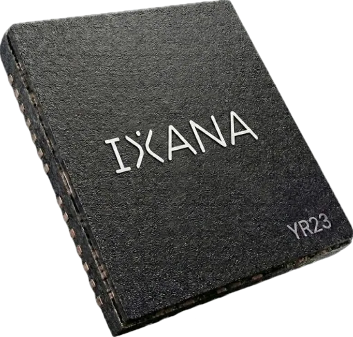
5 Mbit/s Wi-R is shipping in QFN for customer integration.
Wi-R TECHNOLOGY
Localized electric fields connect wearable devices, extend along conductive structures, and bridge short gaps.

The connection stays close to the system
01 THE MECHANISM
Wi-R BAN
Wi-R-enabled wearable devices communicate through a localized electric-field channel.
 Sensing
 Compute
 Interaction
Each participating device needs a Wi-R interface.
Wi-R BAN
Use a suitable conductive structure as part of the communication channel between participating endpoints.
Sensors Compute Control
The structure and endpoint integration must be evaluated together.

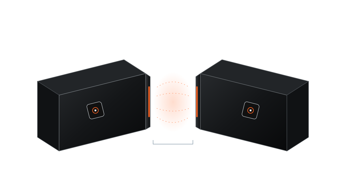
Wi-R NFE
Connect two nearby devices with a localized electric-field link. Wi-R is integrated at both endpoints.
Gap, orientation, and enclosure design are configuration-specific.

Illustrative localized channel; not a measured field map or wireless power.
02 INTEGRATION
A local link connects the devices. Each device still has its own sensing, processing, and power requirements.
ENDPOINT A
Sensor or  Wi-R
Wi-R ENDPOINT B
Wi-R Sensor or Functional data connection; local power remains separate.
01 Integrate Wi-R at both ends
02 Local power remains separate
03 Compute can sit where it fits best
03 PERFORMANCE
Wi-R COMMUNICATION ENERGY
~0.2nJ/bit
About 0.2 nJ/bit, full-chip active TX/RX average at 5 Mbit/s.
NAMED BENCHMARK
38×
Nordic nRF54L15, Bluetooth LE 2M, +4 dBm.
This is an energy-per-bit comparison at stated operating points. It is not a comparison of battery life for a complete product, delivered application throughput, or every Bluetooth implementation.
Energy comparison: Wi-R at 5 Mbit/s, approximately 0.2 nJ/bit, full-chip active TX/RX average. Comparator: Nordic nRF54L15, Bluetooth LE 2M, +4 dBm.
Rate, power, and range must be compared for the same product and configuration.
04 SILICON
5 Mbit/s
5 Mbit/s Wi-R is shipping in QFN for customer integration.
20 Mbit/s
20 Mbit/s silicon is starting to sample. This is separate near-field silicon; the stated rate is the raw PHY rate, not application throughput.
Explore XA-NFE300105 SYSTEM ARCHITECTURE
Sensing, compute, and interaction do not have to live in one enclosure.

Sensing, interaction, and local processing
A wearable sensing endpoint
A location for additional processing
Sensing, feedback, and interaction
Local processing in the glasses and additional pocket compute are two illustrative placements. Wi-R provides the link; the application determines how work is distributed.
Glasses Pocket compute
Distributed sensing along the structure
Tactile and task-specific endpoints
Processing where the architecture needs it
This is an illustrative architecture, not a certified control topology. Timing, fault response, power delivery, and integration across joints need system-specific evaluation.
Illustrative architectures, not deployed reference designs. Numbered leaders identify functional locations, not physical data cables.
06 CHOOSE YOUR CONNECTION
07 GO DEEPER
DEMONSTRATIONS
Explore working Wi-R demonstrations in personal and embedded systems.

TECHNICAL DETAIL
Product briefs and resources for integration
Explore resourcesRESEARCH
The research behind the channel and communication silicon
Explore resources
DEVELOPMENT
Identify the product and starting point for your system.
Explore resourcesBEFORE YOU BUILD
Each participating device needs a Wi-R interface and the host integration appropriate to the chosen product. Start with the relevant product documentation and evaluation hardware.
Data connectivity and power delivery are separate design questions. Evaluate the power requirements of each endpoint in your configuration.
Compare identified products at stated operating points. Distinguish raw data rate from application throughput and IC energy from system power. Treat distance along a structure, distance away from it, and the gap between NFE devices as separate measurements.
Participating endpoints need the corresponding Wi-R integration or an appropriate external interface. An unmodified phone or wearable does not automatically join the system.
EVALUATE Wi-R
Tell us which endpoints need to connect, what data they carry, and what physical constraints apply. Start with your architecture, then choose the silicon.
YOUR STARTING POINT
The participating devices
The data rate and workload
The system layout and device spacing
 Explore developer kits