Sep 28, 2026Shreyas Sen14 min read
Wi-R: A New Architecture for Local, Low-Power Wireless Communication

How Ixana Wi-R uses localized electric fields to connect wearable devices, conductive structures, and nearby devices with low communication energy.
Wi-R: A New Architecture for Local, Low-Power Wireless Communication
Localized electric fields can connect wearable devices, conductive structures, and nearby devices while keeping the communication link close to the intended system.

Modern wireless systems are exceptionally good at moving information through free space. That is exactly what we want when a phone connects to a router across a room, a wearable connects over several meters, or a device needs access to a larger network.
But not every connection needs to fill the room.
A growing class of products needs to connect devices that are already part of the same physical system: glasses and a pocket compute device worn by one person, sensors distributed along a machine, or two powered devices separated by only a short gap.
Wi-R is designed for those connections.
Wi-R uses localized electric-field communication to create data links that stay close to the person, structure, or devices participating in the system. Rather than treating maximum propagation distance as the default objective, Wi-R starts with a different question: where does the connection actually need to exist? [1]
Wi-R in 30 seconds
What: Localized electric-field communication.
Where: On a person, along a conductive structure, or across a short gap.
How: Wi-R is integrated at participating endpoints, while each endpoint keeps its own sensing, processing, and local power.
Performance: About 0.2 nJ/bit, measured as a full-chip active TX/RX average at 5 Mbit/s. [1]
Today: 5 Mbit/s Wi-R silicon is shipping for integration. XA-NFE3001 with a 20 Mbit/s PHY is starting to sample. The 20 Mbit/s figure is the raw PHY rate, not application throughput. [1]
Not every wireless connection needs to fill the room
Traditional radio technologies are built to move information through the surrounding environment. That is a feature when endpoints need to communicate across a room or building.
The physical problem looks different when the endpoints are already:
- worn by the same person,
- attached to the same machine or structure,
- positioned in deliberate proximity, or
- part of the same local sensing and compute system.
In these systems, the useful communication region may be the person, the structure, or the short space between two devices—not the rest of the room.
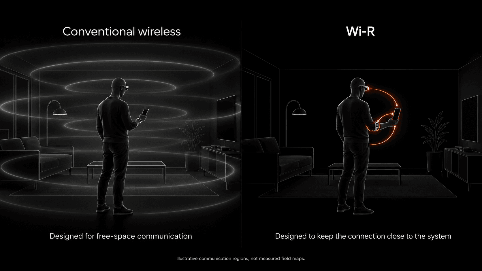
Illustrative communication regions; not measured field maps.
Wi-R changes the design objective from how far can the signal propagate? to how efficiently can the intended endpoints stay connected?
Three ways Wi-R creates a local connection
The simplest way to understand Wi-R is through three physical connection contexts.
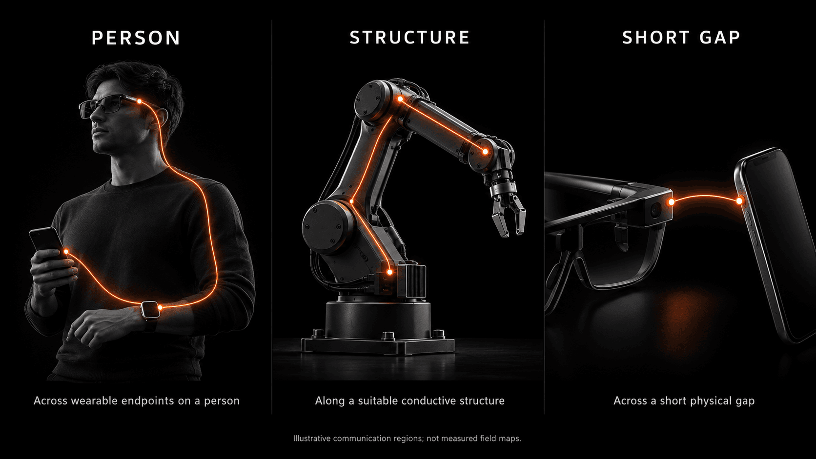
On a person
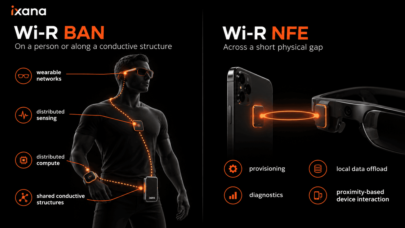
Wi-R BAN connects participating wearable endpoints through a localized electric-field channel. Smart glasses, biosensors, watches, and nearby compute can become parts of one local system instead of behaving only as independent devices.
Along a structure
A suitable conductive structure can become part of the communication channel between integrated endpoints. This creates a path for distributed sensing, compute, and control architectures where the physical structure itself is already shared by the devices.
Across a short gap
Wi-R NFE connects two nearby powered devices through a localized electric-field link. It is intended for local interactions such as provisioning, diagnostics, data offload, and other deliberate device-to-device exchanges. [1]
These are different geometries, but they share the same architectural idea: keep the communication link close to the system that needs it.
A localized electric-field communication channel
At a high level, a Wi-R connection has four parts:
- A Wi-R endpoint generates the communication signal.
- An electrode or coupling structure couples that signal into the local communication environment.
- A second Wi-R endpoint detects the signal through its own coupling structure.
- The receiving interface recovers the data for the local host or processor.
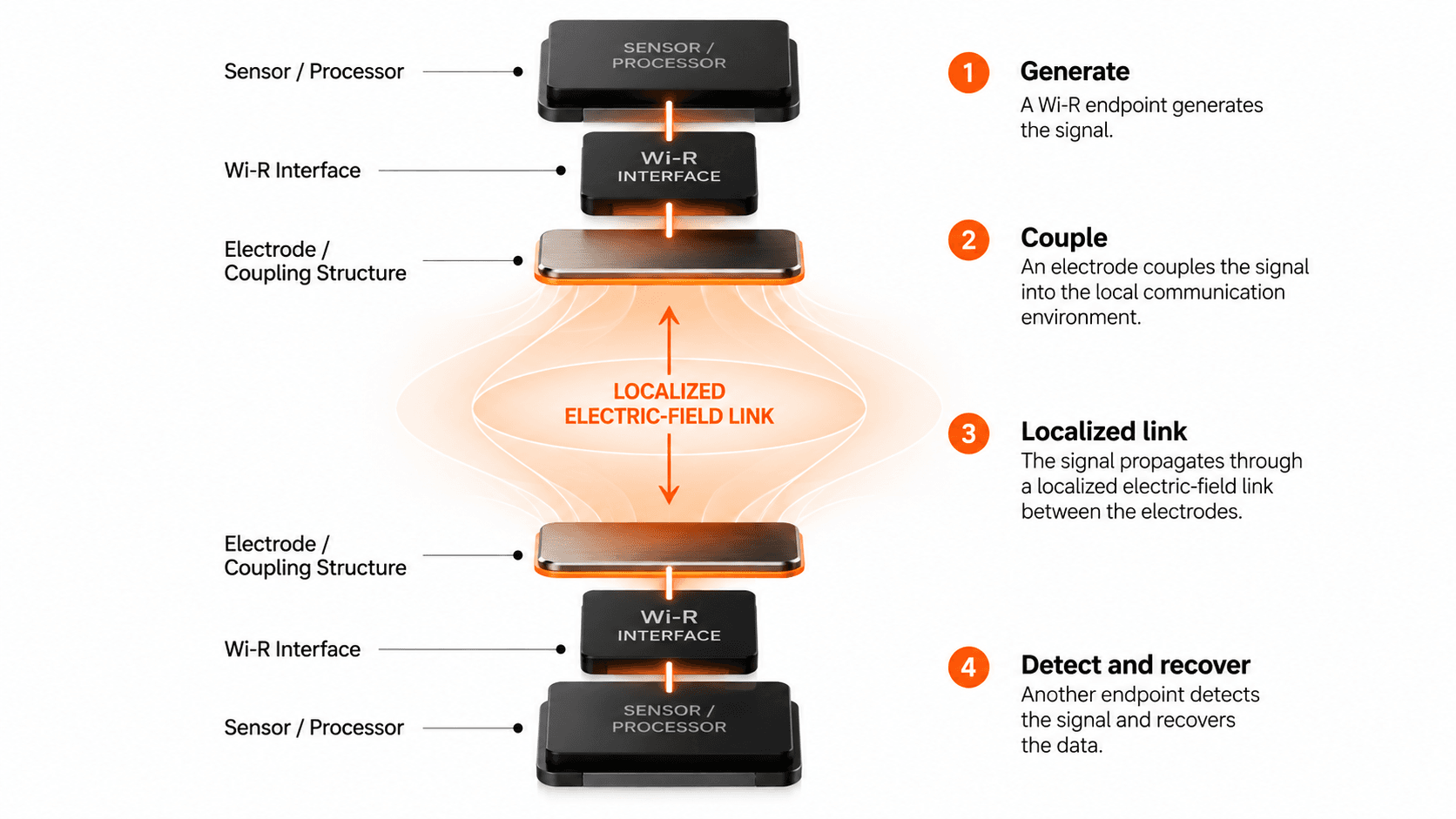
The orange communication region in these diagrams is a conceptual representation. The exact field distribution depends on electrode geometry, enclosure, orientation, surrounding materials, the participating structure, and the selected product configuration.
That distinction matters. Wi-R should be evaluated as an integrated communication system, not as an abstract field shape separated from its endpoints.
What a Wi-R endpoint actually requires
A Wi-R-enabled system is built at the endpoints.
A Wi-R interface
Each participating endpoint needs a compatible Wi-R interface appropriate to the selected product and use case.
An electrode or coupling structure
The coupling geometry is part of the system design. Its implementation depends on the endpoint, enclosure, physical placement, and intended connection context.
Local sensing, processing, and power
Wi-R provides the communication link. Each endpoint still has its own functional requirements—including sensors, processing, memory, and power.
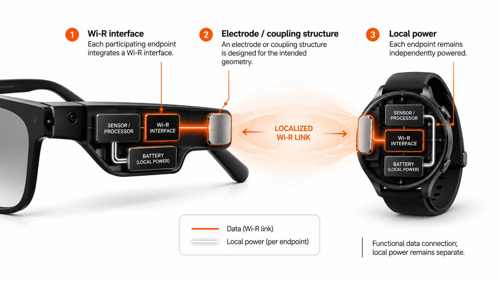
Functional data connection; local power remains separate.
The exact Wi-R interface, electrode/coupling structure, and host integration depend on the selected product and physical configuration. [1]
This separation is important because data connectivity and power delivery are different design questions. Current Wi-R products use the localized field for communication; participating endpoints remain locally powered. [1]
Why communication energy matters
Wearable and embedded products have finite power budgets. Communication competes with sensing, compute, memory, displays, audio, and other system functions for that budget.
For these products, the useful question is not simply how much power a radio consumes at one instant. It is also how much communication energy is required to move each bit of information.
Ixana's current Wi-R technology page reports approximately:
~0.2 nJ/bit
for the full-chip active TX/RX average at 5 Mbit/s. [1]
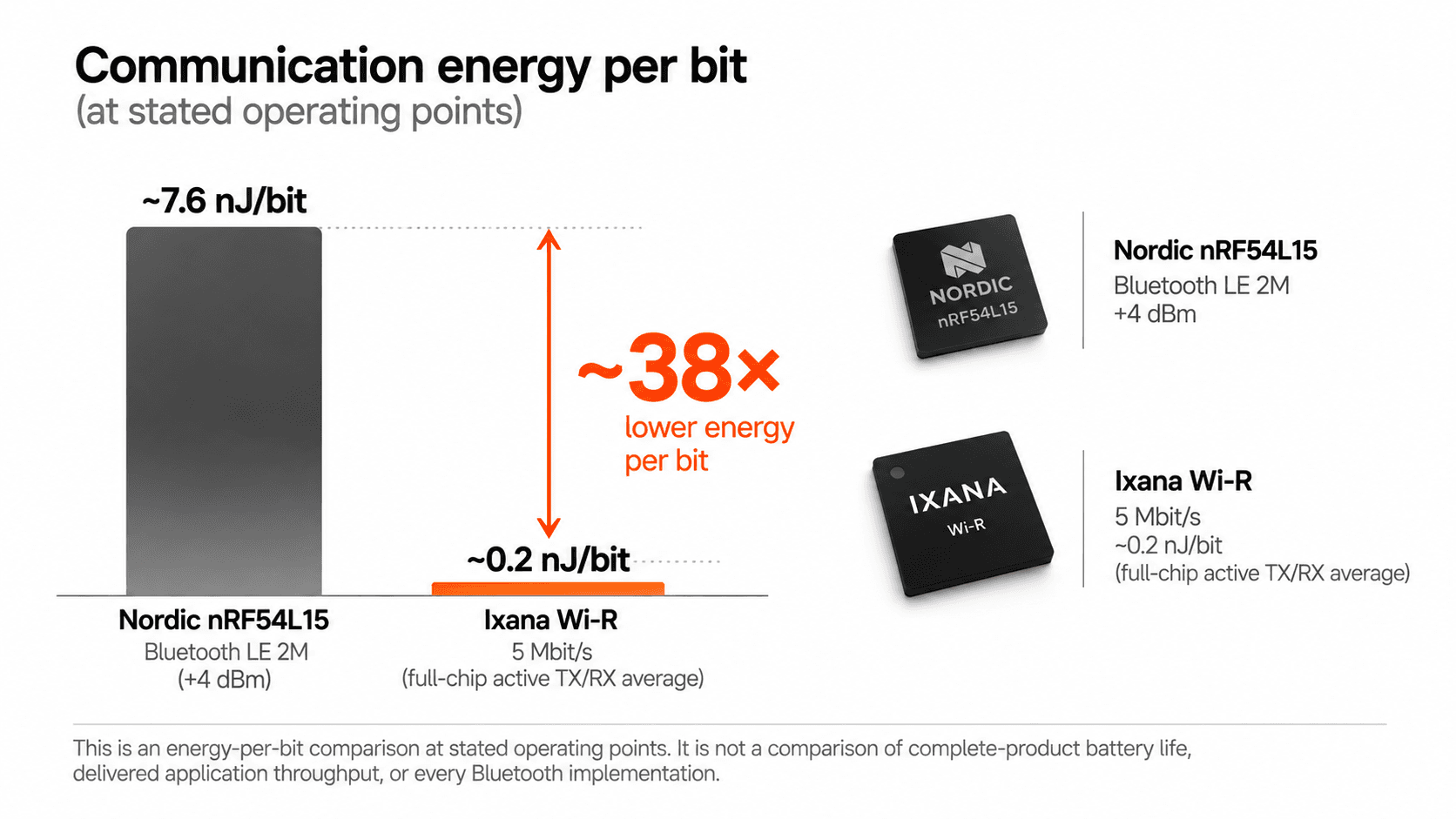
Using the named operating points published by Ixana, this is approximately 38× lower communication energy per bit than a Nordic nRF54L15 operating with Bluetooth LE 2M at +4 dBm. [1]
That comparison needs the operating conditions attached to it.
It is an energy-per-bit comparison at stated operating points. It is not a claim that every Wi-R product will have 38× the battery life of every Bluetooth product. It is not a comparison of delivered application throughput, complete endpoint power, or every Bluetooth implementation.
The application-level result depends on the complete system and workload.
That is precisely why energy per bit is useful: it isolates the communication cost so system designers can decide where the saved power budget is most valuable.
The architecture is already in silicon
Wi-R is no longer only a research architecture.
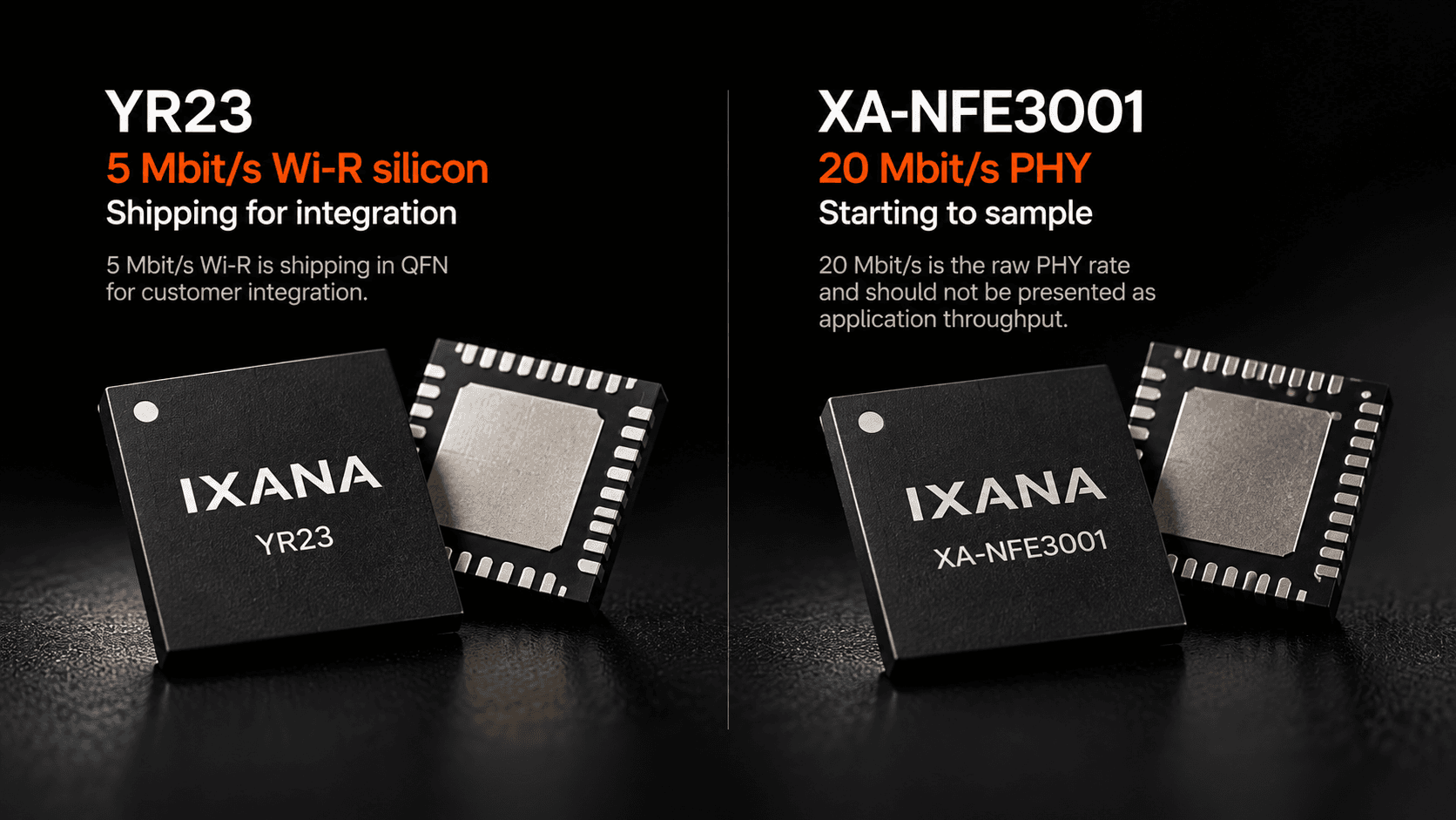
YR23 — 5 Mbit/s Wi-R silicon
Shipping for integration
5 Mbit/s Wi-R is shipping in QFN for customer integration. [1]
YR23 provides a concrete starting point for systems that need the current 5 Mbit/s Wi-R generation.
XA-NFE3001 — 20 Mbit/s PHY
Starting to sample
XA-NFE3001 extends the near-field platform to a 20 Mbit/s raw PHY tier. The stated 20 Mbit/s rate should not be interpreted as application throughput; protocol, interface, and application overhead determine the delivered payload rate. [1]
BAN or NFE?
The most important product decision is not simply data rate. It is the physical relationship between the endpoints.
Wi-R BAN — along a system
Wi-R BAN is designed for communication on a person or along a suitable conductive structure.
Typical architectural uses include:
- wearable networks,
- distributed sensing,
- distributed compute,
- multiple endpoints around one person, and
- sensing and compute distributed along a structure.
Wi-R NFE — across a gap
Wi-R NFE is designed for a short physical gap between powered devices.
Typical architectural uses include:
- provisioning,
- diagnostics,
- local data offload,
- sealed or portless access, and
- intentional proximity-based interactions.
Neither mode is intended to replace every other wireless technology. The point is to choose a communication architecture that matches the physical system.
A local network for wearable systems
Wearables are increasingly becoming systems rather than individual devices.
A pair of smart glasses may be the best place for cameras, displays, and user interaction. A watch or biosensor may be the best place for continuous sensing. A pocket device may have more space for battery and compute.
Forcing every function into one enclosure creates its own power, thermal, weight, and ergonomic constraints.
Wi-R BAN creates a local communication layer between participating endpoints so those functions can be distributed physically.

The system can then be designed around function rather than around the assumption that all sensing and compute must live in the same device.
Distributed devices need a local interconnect
The architecture becomes easier to reason about when the functions are separated into three questions.
Sense where the sensor needs to be
Cameras belong where they have the right viewpoint. Biosensors belong where they can measure the intended signal. Motion sensors belong where the motion occurs.
Compute where power and thermals allow
Some processing may happen locally. Other workloads may be better suited to a pocket device, phone, or embedded compute module with a different thermal and battery envelope.
Interact where ergonomics work best
Displays, audio, touch, haptics, and other interfaces can remain where they make sense for the user.
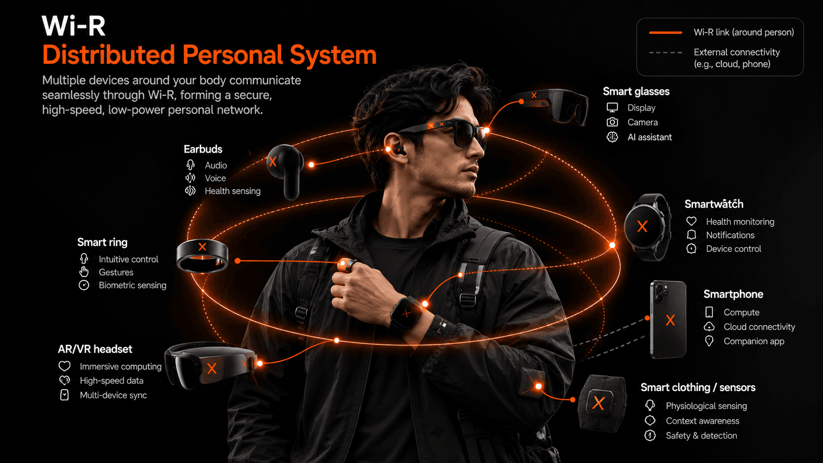
Sensing, compute, and interaction do not all need to live in the same enclosure.
Wi-R provides the local interconnect. The application determines how the work is distributed. [1]
The same architecture can extend along structures
The same system-level idea is not limited to people.
When multiple endpoints are attached to a suitable conductive structure, that structure can become part of the Wi-R communication path.
Consider an articulated robotic or industrial system with sensing distributed across joints and an end effector. The useful architecture may place sensing where the physical event occurs and compute or control elsewhere in the system.

Possible functional locations include:
Joint sensing. Distributed measurements along the structure.
End-effector sensing. Tactile or task-specific endpoints close to the point of interaction.
Compute and control. Processing where the architecture needs it.
Illustrative architecture; not a certified control topology. Timing, fault response, power delivery, safety, and integration require system-specific engineering and validation.
The purpose of the example is architectural: a local interconnect can allow sensing and compute to be distributed without requiring every endpoint to communicate as an independent room-scale radio node.
Bridge the short gap with Wi-R NFE
Some local connections do not share a body or structure. The devices are simply close together.
Wi-R NFE addresses that geometry.
Both participating devices integrate Wi-R and remain independently powered. The communication channel bridges the short physical gap between them.
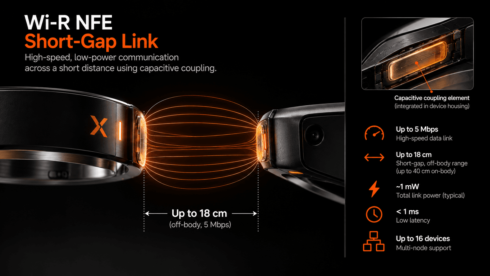
Illustrative communication region; not a measured field map or wireless-power depiction.
The useful operating gap is not one universal number. It depends on product selection, electrode design, device orientation, enclosure materials, and the selected operating point.
This makes NFE suitable for applications where deliberate physical proximity is already part of the product behavior, including setup, service, diagnostics, and local data transfer.
A different design space for connected systems
Localized communication becomes more important as systems become more physically distributed.
More distributed sensing
The number of sensing locations is increasing. Glasses, watches, patches, rings, cameras, machine joints, tools, and other endpoints all create data where they physically operate.
More distributed compute
Processing does not have to happen in the same enclosure as the sensor. It can move to a device with a better power, thermal, or form-factor envelope.
More constrained endpoints
Wearable and embedded products still have strict limits on size, weight, battery capacity, thermal dissipation, comfort, and mechanical design.
When functions are physically distributed, the local interconnect becomes part of the system architecture.
That is the design space Wi-R is intended to address.
Where localized connectivity can matter
Smart glasses and XR
Connect sensing and interaction devices to nearby compute without assuming that every workload must remain in the glasses.
Wearable sensing
Connect multiple participating endpoints around one person for continuous sensing, feedback, and distributed processing.
Portless diagnostics
Retrieve data, configure a device, or perform service interactions without requiring an exposed physical connector.
Local data offload
Move images, logs, firmware, or other payloads between nearby devices when intentional proximity is already part of the workflow.
Robotics and industrial systems
Connect distributed sensing and compute endpoints along suitable conductive structures, subject to the application's integration and safety requirements.
Healthcare and constrained sensing
Provide a local communication option for form-factor- and power-constrained sensing systems where endpoint placement matters.
These applications do not all require the same Wi-R mode, electrode implementation, or operating point. The architecture must be selected for the actual geometry and workload.
From research to silicon
Wi-R grew from electro-quasistatic communication research at Purdue into packaged communication silicon and development platforms.
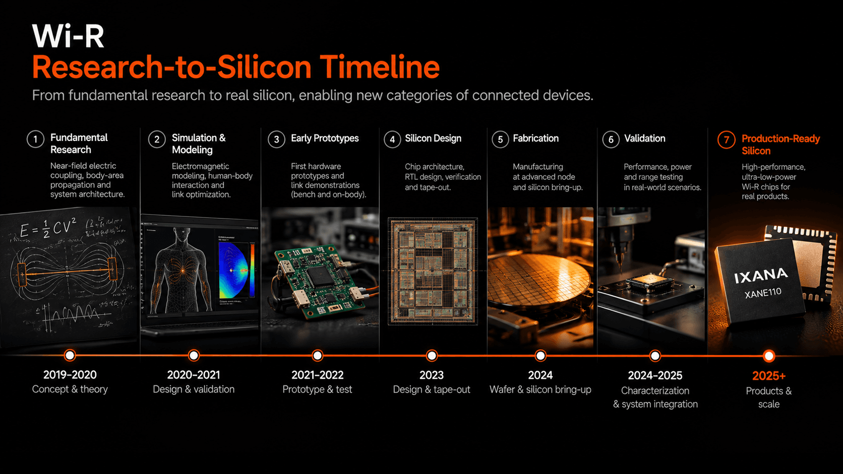
2016 — Research starts at Purdue
2021 — 10 kbit/s test silicon
2023 — 1 Mbit/s demo
2025 — 5 Mbit/s shipping
2026 — 20 Mbit/s sampling [2]
The roadmap continues beyond today's products, but future throughput and capability targets should be read as roadmap items rather than current product specifications.
A few practical questions
Does every participating device need Wi-R?
Yes. Each participating endpoint needs a compatible Wi-R interface and the host integration appropriate to the selected product. [1]
Does the Wi-R data link also deliver wireless power?
No. Current Wi-R data connectivity and endpoint power delivery are separate design questions. Each endpoint must meet its own power requirements. [1]
Can an existing phone participate?
Participating endpoints need the corresponding Wi-R integration or an appropriate external interface. An unmodified phone or wearable does not automatically join the system. [1]
What determines range and performance?
The answer depends on the connection context and selected product. Electrode geometry, enclosure, orientation, host integration, physical layout, data rate, and operating point all matter.
Distance along a structure, distance away from a structure, and the gap between NFE devices are different measurements and should not be treated as interchangeable. [1]
How should Wi-R be compared with another wireless technology?
Compare identified products at identified operating points. Distinguish raw PHY rate from application throughput, IC communication energy from complete system power, and the different physical definitions of range.
Evaluate Wi-R in your system
A useful evaluation starts with the architecture, not with a generic radio specification.
01 — See working demonstrations
Understand how the physical link behaves in representative systems.
02 — Review the technical evidence
Inspect product documentation, measurements, application material, and the underlying research.
03 — Select BAN or NFE
Choose the connection context that matches the system: on/along the system with BAN, or across the short gap with NFE.
04 — Evaluate in the intended environment
Validate throughput, latency, communication energy, electrode configuration, enclosure effects, spacing, and host integration in the actual product geometry.
Keep the connection close to the system
Wi-R starts from a simple premise: many connected devices do not need another room-scale link. They need an efficient connection to the person, structure, or nearby device that is already part of their system.
That changes how the interconnect can be designed.
Evaluate Wi-R for wearable devices, conductive structures, and short-gap links.
References
[1] Ixana, "How the wireless wire works — Wi-R Technology."
[2] Ixana, "Wi-R Platform Roadmap."
[3] Ixana, "Wi-R BAN."
[4] Ixana, "Wi-R NFE."
[5] Ixana, "Developer Kits."
Wi-RWi-R BANWi-R NFEWearablesDistributed computingNear-field communicationElectro-QuasistaticSemiconductorPhysical AI

Shreyas Sen
Elmore Associate Professor of ECE & BME at Purdue, Founder & CTO of Ixana, MIT TR35, TEDx, GT 40U40
Illustrative use case only. This page describes example workflows and interoperability concepts involving Ixana Wi‑R technology and third-party systems. Unless expressly stated otherwise, Ixana provides communications silicon, circuit boards and firmware components for E-field based body-area-network and near-field data transfer and is not offering complete medical device, clinical triage system, or finished end products.